Difference between revisions of "DIY Plastics Kit"
(Added new step 2 for manually upgrading the firmware.) |
(→Step 2: Update Firmware: added video link and verbiage to re-insert the microSD) |
||
| Line 22: | Line 22: | ||
===Step 2: Update Firmware=== | ===Step 2: Update Firmware=== | ||
| − | The NeTV ships with firmware version 25 on the microSD card. There have been reports that the automatic firmware update is problematic. It will be much easier to upgrade the firmware manually '''before''' you continue the rest of the assembly | + | The NeTV ships with firmware version 25 on the microSD card. There have been reports that the automatic firmware update is problematic. It will be much easier to upgrade the firmware manually '''before''' you continue the rest of the assembly. |
| − | [[File:NeTV-SD-location.jpg|400px | + | First, remove the microSD card from its holder as indicated in the image below. The holder is delicate and not spring loaded. Here's a video showing the same mechanism but in a [https://youtu.be/LaNbdeLzj4s?t=329 Blackberry phone]. You only need to watch it for about 20 seconds. |
| + | |||
| + | Second, [http://bunniefoo.com/netv/rom-chumby-silvermoon-netv-chumby-image-r43.zip download the latest firmware image]. It is a 70MB zip file and when uncompressed it'll be 1GB. | ||
| + | |||
| + | Third, follow the steps to [https://kosagi.com/w/index.php#Burning_images_to_disk burn the image to disk]. | ||
| + | |||
| + | Finally, re-insert the microSD card. | ||
| + | |||
| + | [[File:NeTV-SD-location.jpg|400px]] | ||
===Step 3: Antenna Attachment=== | ===Step 3: Antenna Attachment=== | ||
Revision as of 20:24, 14 October 2016
Contents
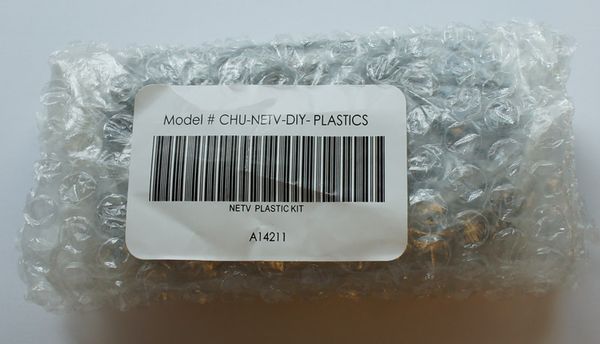
Out of the box
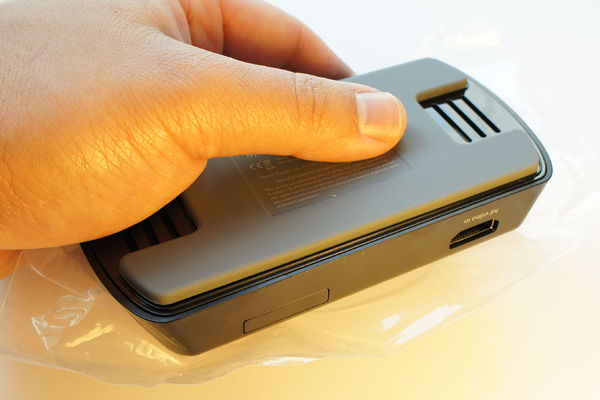
Out of the box, the DIY kit is a compact, bubble-wrapped set of parts.
Contents
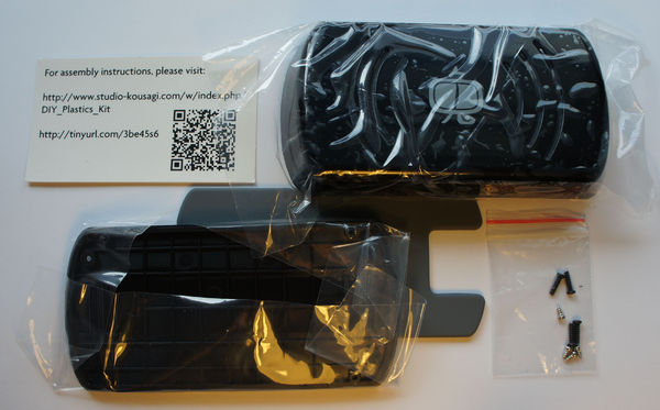
The kit should contain the following contents:
- A card pointing to this URL
- The top of the plastic case
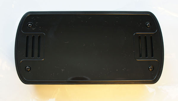
- The base of the plastic case
- A rubber foot for the plastic case
- Four long screws (PB2.3x8mm self-tapping cross head screw)
- Four short screws (PB2.3x4mm self-tapping cross head screw)
Step 1: Mainboard Attachment
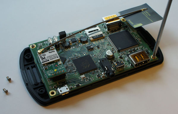
Attach the mainboard to the case using the four short screws.
Step 2: Update Firmware
The NeTV ships with firmware version 25 on the microSD card. There have been reports that the automatic firmware update is problematic. It will be much easier to upgrade the firmware manually before you continue the rest of the assembly.
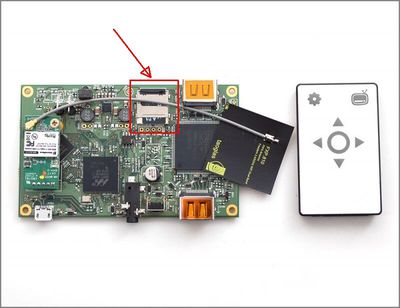
First, remove the microSD card from its holder as indicated in the image below. The holder is delicate and not spring loaded. Here's a video showing the same mechanism but in a Blackberry phone. You only need to watch it for about 20 seconds.
Second, download the latest firmware image. It is a 70MB zip file and when uncompressed it'll be 1GB.
Third, follow the steps to burn the image to disk.
Finally, re-insert the microSD card.
Step 3: Antenna Attachment
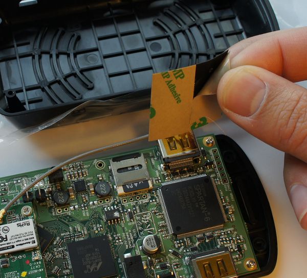
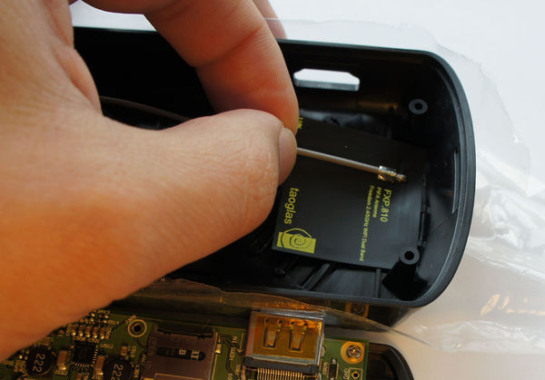
Peel the adhesive tape off of the back of the wifi antenna, and attach the antenna to the top case, paying attention to the following important rules:
- The antenna must be on the side of the case with the HDMI ports (the side without the word "bunnie" on it)
- The antenna must be kept as flat as possible (do not wrinkle the membrane as you apply it)
- The antenna should be as close to the case edge as possible without curving the antenna itself
The active element of the antenna is a thin strip about 1cm wide near the outer edge. The case is designed to ensure the active elements clear the HD video ports, but this clearance is only satisfied if the antenna is mounted right up to the edge of the case. However, because the case has a curvature to it, it is easy to go too far and mount the antenna so that the corners are bent slightly due to the case's curvature. The bending of the corners can greatly affect the radiation efficiency of the antenna; thus the mounting needs to be very precise.
Despite the strong warnings, you won't damage anything if you mount the antenna incorrectly; you will simply have non-optimal RF performance.
Step 4: Snap Case Together
Before starting this step, take a moment to observe that the inner plastic wall of the "HD video in" port has grooves designed to enable the HDMI connector to slide against the plastic wall. Note that the opposite "HD video out" port lacks these grooves.
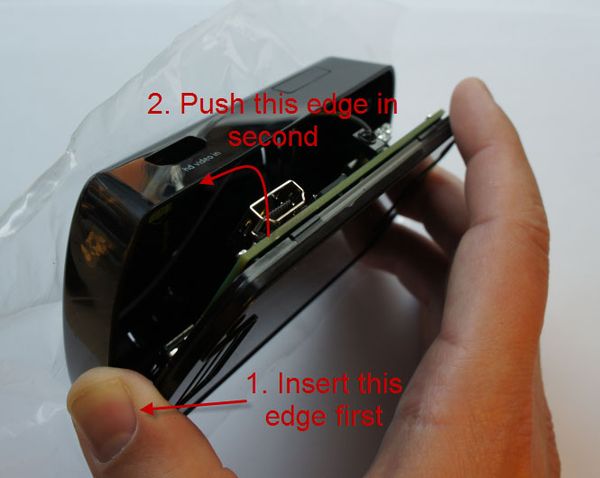
In order to snap the case together, one must first align and insert the "HD video out" side of the motherboard to the top case. This is the side with the switch, IR jack, and HD video out port. Once this is aligned, you can push the other side of the case in.
See the image below for the alignment order.
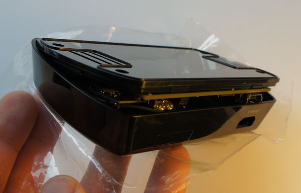
Before pushing the case together, you may need to flex the plastic wall near the HD video in connector. The plastic is designed to handle this kind of flexing. The case should look something like the following the instant before you snap the two halves together.
Note that if you reverse the assembly order of the sides, you will apply a traumatic amount of stress to the HD video out connector and the IR extender connector.
Step 5: Affix Retaining Screws
Use the remaining screws to fix the two halves of the case together. If you intend to take the unit apart fairly often, you may omit the screws, as the HDMI connectors and snap hooks do a pretty good job of holding the case together and planarizing the assembly.
Step 6: Affix the Rubber Foot
Peel the backing off of the rubber foot and attach.
Step 7: Remove Anti-Fingerprint Wrap
If you haven't done so, remove the anti-fingerprint wraps. It is strongly recommend that you do this because otherwise the cooling holes on the top of the case are obstructed.
